 Promit's Ventspace
 This is the result of several years of work and testing now, and I’m happy to finally publish it for everyone. All of the text, design, and artwork in this post are under the Creative Commons CC-BY license. That is, you are allowed to modify and share as you wish as long as I, Promit Roy, am credited as the origin. I also politely ask, but do not legally require, that you let me know if you build or modify these and share your own images.
I’ve been working on this for a long time, and it’s finally evolved to the point that I’m able to share the full design and build instructions for this dance pad. I know Dance Dance Revolution is a blast from the past for most, but it continues to be something I enjoy a lot. Unfortunately as its commercial popularity has faded, so has the range of products for those who are still playing via StepMania on a PC platform. Most people go with the expensive Omega GX pads, which are built as a family business effort in the USA. I support their work, but DIY saves some money and is always more fun too.
If you are within traveling distance of northern Baltimore, MD and would like to try the pad in person, please contact me and we can work something out.
There have been plenty of DIY pad designs published or shown over the years, using a variety of materials. Most common designs are meant to emulate full arcade play, with a heavy wood/steel base and high effort steps. These tend to have poor edge/corner sensitivity, high pressure requirements, and significant weight and bulk making them difficult to move and store. Some use foam spacers which don’t have sufficiently consistent or precise behavior for serious play. There are frequently sharp or hard metal and screw edges that are quite unpleasant on bare feet. I’ve also observed reliability problems as the sensors are susceptible to dirt ingress, weather strip or foam edging slowly wears, and some designs (including Omega) use foil contacts that are susceptible to tearing.
I believe I have managed to solve all of these problems. Using a material called “Velostat”, I’ve designed and built a new style of sensor that is solid state and completely sealed. Nothing tears. Nothing moves. There is nowhere for dust to enter. It’s sensitive to ounces of pressure. Indeed you can simply mount four of these sensors to a plywood board, wire it up, and play. The lack of moving parts means there is no tactile feedback in the sensor itself however, and most of the design work is about designing an inexpensive pad around these sensors which does offer tactile feedback and good aesthetics. It’s easy to build and quite forgiving about mistakes. The sensitivity is also easily tweakable after it’s built. While it’s not especially cheap, I believe that this design is near indestructible and sufficiently precise for competition-level play.
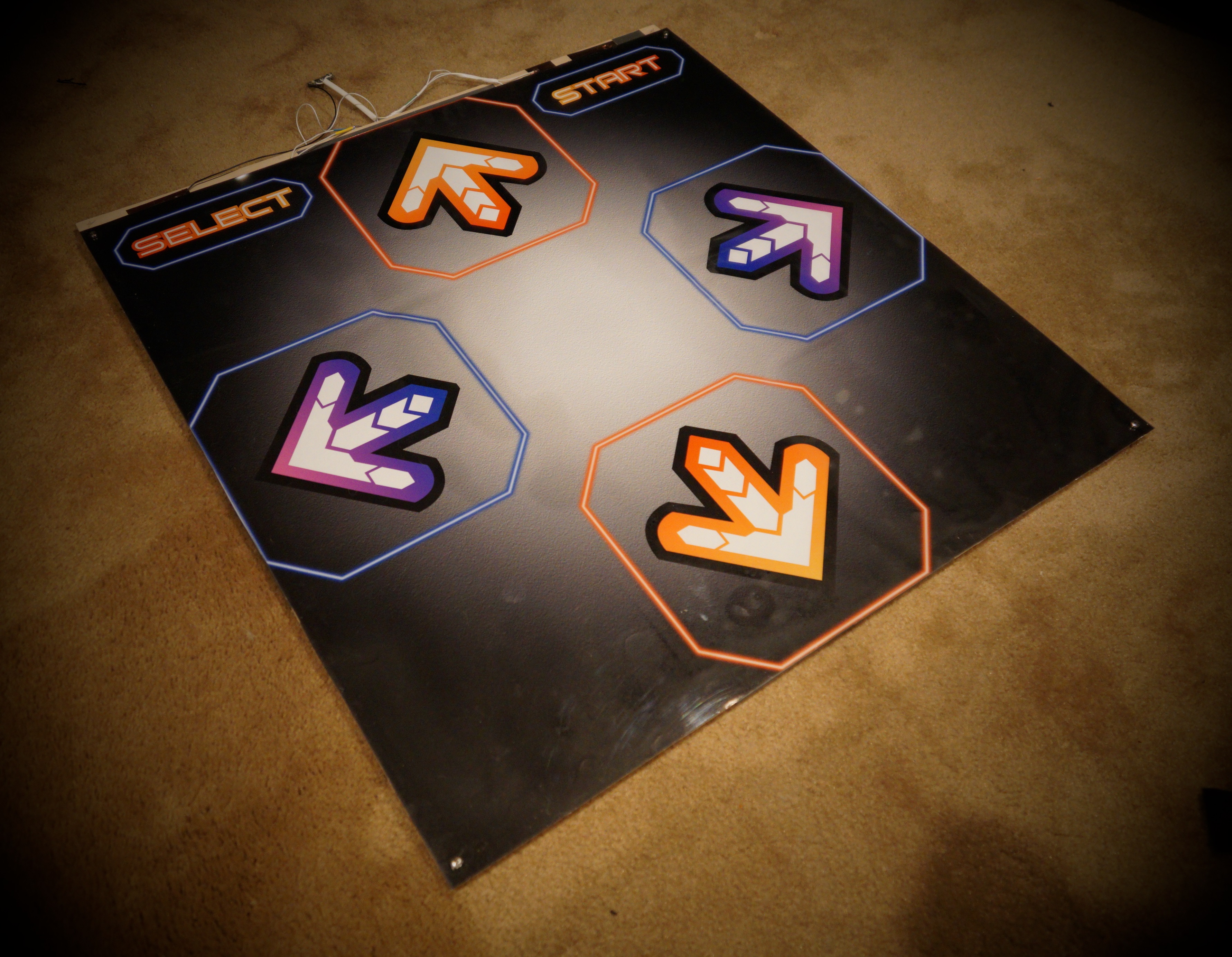
This is the Version 3 slimline pad. Version 1 was quite complex and bulky, had some reliability issues due to its removable modular sensors, but worked reasonably well as a proof of concept. Version 2 was an attempt to ditch the MDF and carve channels in plywood. It warped badly over time. This version cuts down significantly on bulk, complexity, and cost while improving sensitivity. I have some ideas for a future Version 4, see the bottom of the page.
I’m also working on a fairly cheap way to convert the whole thing to Bluetooth wireless, which will hopefully work in the near future.
Bill Of Materials and Cut List
All together, the cost is about $220 per pad (incl. non-stick bottom, which Omega doesn’t provide). I’ve compiled the complete material list below. I have linked to the exact items I purchased in construction; none of these are affiliate links and I don’t see a dime if you click on them. If price is a concern, the poster graphic and spray mount glue are optional and can be added later. The non-slip pad can be omitted on carpet or replaced with a rubberized (Plasti-Dip) spray.
- 48” x 96” plywood sheet - makes two pads. I have Home Depot cut these to 36” square to fit them in my car. My slimline build uses 1/4”, which is lightweight but allows some flex on carpet. If you want a heavy duty pad or dislike pad flex, you can upgrade to thicker sheets (1/2” or even 3/4”) - just buy equivalently longer M5 screws. Make sure the plywood is not warped!
- 24” x 48” x 1/4” MDF sheet - Enough for one pad, with a fair bit of scrap.
- 48” x 96” x 0.040” Lexan/polycarbonate sheet - makes two pads. Try making an offer, I have seen it on sale for a lot less than the $118 list price. This 40 mil works well, I have tested as thick as 0.093” (Home Depot stock) and it works but makes the steps significantly stiffer. I don’t recommend sizing down to 0.030”. I also don’t recommend acrylic, plexiglass, etc. Update 2/12/2019: It appears that there’s been a massive price spike in my preferred choice of Lexan sheet. This 0.060” thick material ($80) is my current replacement recommendation, and this seller will cut for free.
- 2” copper conductive adhesive tape - Used for base contact layer, reduces the amount of sheet metal and soldering required. Probably enough to make a whole bunch of pads.
- 36” x 36” x 0.019” aluminum sheet metal - Unfortunately we need five out of nine square feet here. You’ll have leftovers.
- 5x Velostat/Linqstat sheet - The heart of it. If out of stock at Adafruit, try Tinkersphere instead.
- EPDM rubber weather strip tape - It’s important that you get the D-profile stuff that splits in half. Do not get normal “rubber foam” weather strip. The consistent springiness of EPDM works very well here.
- Gorilla felt/rubber rug pad 4’ x 6’ - optional but highly recommended non-slip layer, makes two pads, keeps things in place pretty well.
- 3M 90 Adhesive spray - don’t need a lot. You can probably substitute many other adhesive sprays.
- Titebond II or similar wood glue - If you have any wood glue lying around, it should work just fine.
- 2x M5-0.8 3 Pack T-Nut - That’s six in total.
- 3x M5 x 12 mm 2 pack pan head machine screw - DO NOT buy flat head. PAN head only!
- Gorilla Tape 1-7/8 x 12 yards - Would it even be a DIY project without duct tape? Any duct tape is probably fine.
- 33” x 33” Luster-Satin poster print graphic - technically optional, but looks fabulous. I have a free design linked down below, but print anything you like. About $25.
- Scotch Spray Mount adhesive - this oddly expensive glue is perfect for mounting the poster to the top Lexan sheet.
- 22 AWG stranded wire or similar - anything light gauge stranded will do fine. Light speaker wire or lamp cord or whatever. Don’t go heavier than 18 AWG. I suggest a white roll and a black roll.
- Teensy-LC - the Arduino-compatible brainbox for the pad. For those who are technically savvy, any of the various m0 boards will work just fine, with some small code tweaks.
Below is the cut list from the materials purchased above:
- 34” x 33” plywood
- 2x 33” x 33” x 0.040” Lexan, do not remove protective sheet
- 2x 10.25” x 10.25” MDF
- 2x 5.25” x 10.25” MDF
- 9.5” x 9.5” MDF
- 4x 5” x 1” MDF strips
- 4x 10.75” x 10.75” sheet metal, corners slightly clipped
- 2x 4.5” x 8” sheet metal, corners slightly clipped
- 4x 11.25” Velostat sheets
Note these dimensions are for a borderless version. Some tweaks are required for a classic style with borders. Finally, you will find these useful:
- The Arduino/Teensy sketch code
- My poster image, if you don’t want to make your own (33” x 33” @ 300 dpi)
Make sure to file the cut edges of the sheet metal to smooth. You don’t want a sharp edge to cut into the Velostat, as that will short the sensor. Everything is set up with a little margin, which is necessary but also helps make the design a little more forgiving.
 Cutaway diagram of a sensor sandwich. Two electrical contact layers are separated by a Velostat layer. When compressed, the Velostat resistance drops and the button is triggered.
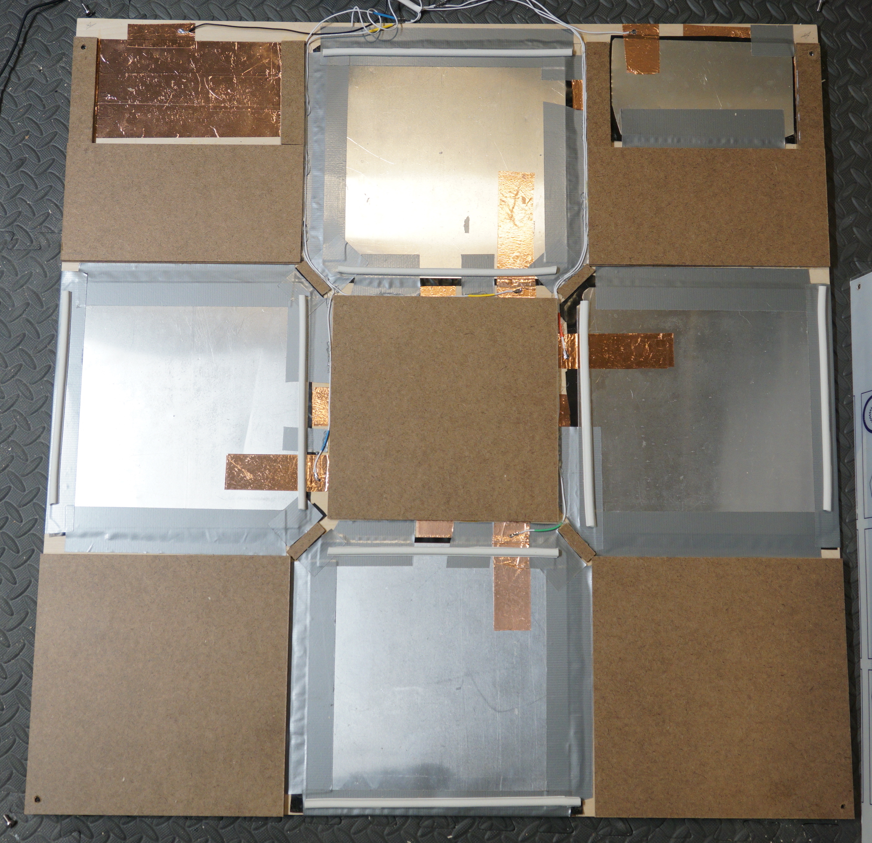 Overall view of the internal pad architecture, for reference. Note: this is a prototype so a few things vary slightly from the text description.
[gallery ids=”1630,1631” type=”square” columns=”2”]
And awaaaay we go!
Build Instructions
- The pad is slightly oversized, with a margin at the front edge. Use pencil to mark off that edge on the plywood, and then divide the rest into a 3x3 grid of 11” squares. These lines will provide the guides for the rest of the build.
-
Cut 11” strips of the copper tape, and lay it down to cover each sensor location. Overlap the strips by 1” to ensure good conductivity across the surface.
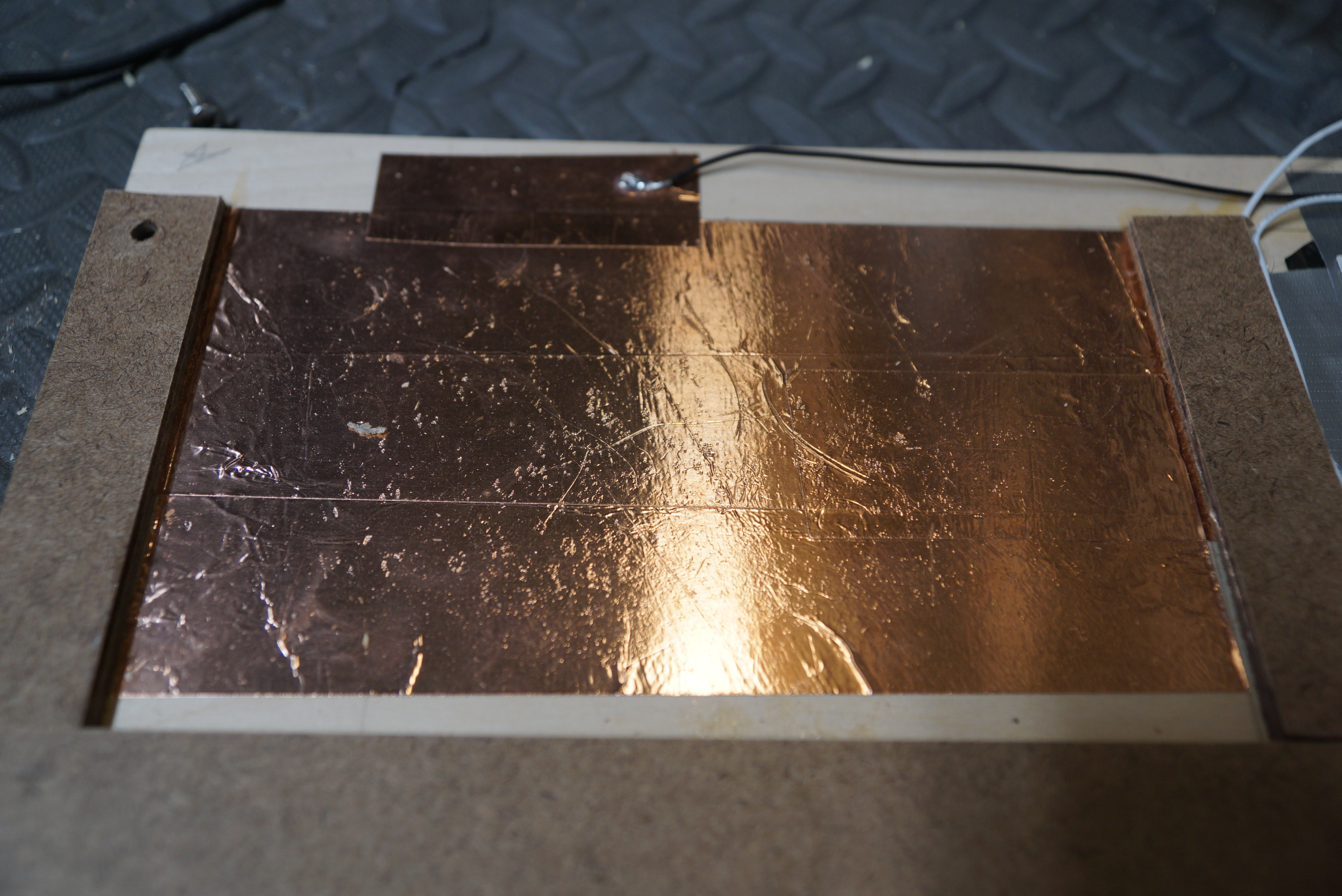 Close-up of the lower contact for the Select button.
 - Pull two long strips of copper tape between the L/R and U/D sensors. Pull two more strips to the Start/Select sensors. Together with the Start/Select sensors (#5), these form our common contact.
- Using wood glue, glue the MDF to the plywood in the non-sensor corners. Large squares in the back corners, smaller square in the center, rectangles in the front corners. Place them 0.75” from the guidelines. Since this is awkward to clamp, I stacked a bunch of textbooks on top to set the glue, at least 30 minutes.
-
Add the MDF strips along the edges of the upper corners to sit around the Start/Select buttons.
 MDF laid out to frame the upper corner buttons.
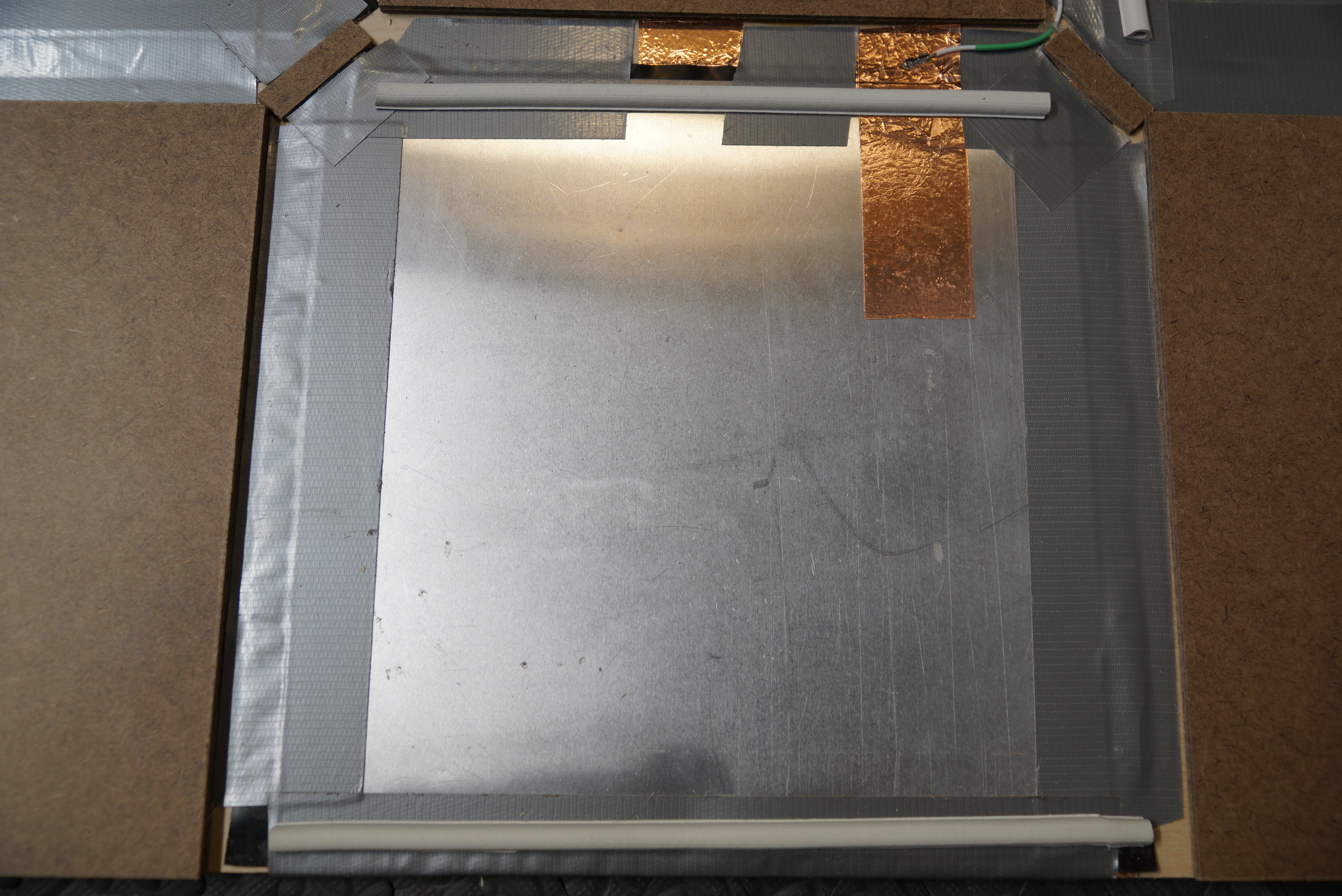
 - Place one Velostat sheet over each sensor location. It should cover the entire copper contact below it, except for the strip that exits to the other sensors. You may optionally glue it down but it’s not necessary. There should be a little space left between the Velostat and the MDF where the plywood is still visible.
- Place sheet metal top contacts over each Velostat sheet. It is critically important that these sheets do not touch copper directly anywhere. Make sure your Velostat has no tears, and isn’t bunching up. The cuts are set up to leave some margin.
-
Attach copper tape from the sheet metal to the inner cable channel of the pad. This is our ‘hot’ connector. DO NOT allow this to come in contact with the copper from the common under any circumstances. If you accidentally have copper showing under and past the Velostat, use electrical tape to block it. It’s fine for the top copper layer to touch the Velostat.
 Less duct tape on the corner buttons, which makes it easier to see the layering here.
 -
Duct tape the sheet metal and Velostat down to the pad as one sandwich. Make sure to tape down all four edges well, but avoid putting duct tape over the copper tape.
 A completed sensor with tape and weather strip.
 - Glue down the MDF corner mini-strips, leaving a little space for wires to route. These strips ensure clean corner separation between steps.
-
It’s now time to route all of the internal wiring. Solder one end of a white wire to a hot contact, then route it through the pad’s internal channels and out the top. You can use the left or right side, but it’s easier if you choose just one. Cut it off with plenty of lead to spare, 8-12” recommended.
 Wire soldered to a contact and routed out. I used colored heat shrink to label them.
 - Choose somewhere to connect a ground wire and run it out the top as well.
-
Use a glue gun to strategically place glue blobs along the wires so that nothing will move around. You want to keep these out of the way of the steps.
 Close-up of the MDF corner pieces, and the wire routing with glue.
 - Split the weather strip, cut it into 11” pieces, and place it on the top and bottom of each main sensor (not start/select). It should be sitting on top of the sheet metal and duct tape, right on the edge.
- We need to align the top properly and make mounting holes. Place the Lexan down first, ideally propped up on something. Then place the pad MDF-down on top of the Lexan so your entire pad is face down. Line everything up and clamp it. Cheapie spring clamps work fine.
- Using a 1/4” drill bit, put holes in the four corners of the pad so they go through all layers. Unless you’re really consistent about how you do it, this step will lock down the Lexan’s orientation relative to the pad so you might want to use a pen to mark that on the protective sheeting.
- Hammer T-nuts into the four holes on the plywood side. Thread the M5 screws in from the other side to secure the Lexan, and then flip the whole thing face up.
-
Congratulations, your pad is mechanically complete! Try it out, give it a few good stomps, see how it feels. All of the buttons should have a nice deep clicky feel. If they seem too deep, we can fix that later.
 She’s not pretty yet, but she is fully functional.
 -
It’s time to connect the brains of the operation. The easiest way to do this is to cut a set of new white wires and solder them separately to the Teensy board’s analog inputs. I used pins 14, 16, 18, 20, 22, and 23 corresponding to A0, A2, A4, A6, A8, and A9. That left a little space between the main wires for my hamfisted soldering. If you change it, or you’re not using the Teensy LC board, remember to update the code accordingly. Then you can pull the wires through some heat shrink, and solder them to the pad’s internal wires.
 No one would mistake my soldering for a skilled hand, but it works.
 - We need to upload the code to the Teensy now. This will require you to install the Arduino and Teensy apps, the instructions for that are here. Once it’s set up, connect a USB cable between Teensy and your computer, load Arduino, and check that everything seems sensible. You might want to load File -> Examples -> Teensy -> Tutorial 1 -> Blink and run it to check that all is well with your board. This is all covered by the Teensy tutorial.
- Make a new sketch file and copy-paste my code into it. Go to Tools -> USB Type and make sure it’s set to Serial + Mouse + Keyboard + Joystick. We only really wanted the Joystick but that’s okay. Go ahead and run the code, hopefully it will load with no issue.
- At long last, we can check if the pad works! Stepping on any step should illuminate the on-board LED, and it should be off otherwise. If it’s lit when you’re not touching anything, you have a short and need to figure out which signal is bad.
-
Assuming nothing has gone wrong, you now have a playable pad! This is a good time to play some test rounds of Stepmania and make sure everything fully checks out.
 Hot glued the hell out of the wires to secure them. Be neater than this.
 - If you’re using the non-slip layer, cut it to size. Spray a bunch of glue on it and on the back side of the plywood, then stick em together.
- To finish up the cosmetics of the pad, unscrew the Lexan and remove the protective film from the inside face of the sheet. Don’t lose track of which side is which! Place the graphic face down on the Lexan, and double check you have everything pointed the right direction. When you’re comfortable that everything is correct, use the spray mount adhesive to glue the poster to the Lexan. The more evenly you can spray the glue, the better it will look.
- Now use a utility knife to cut notches for the screws in the poster, and secure your Lexan sheet back to the top of the pad. We are done!
I admit on a first read through, that sounds like a lot of work. It’s actually not that bad, and I spent a fair bit of time simplifying the design so that it would all go together smoothly. The key to the design is understanding how the sensor sandwich is put together. Everything else is just window dressing around those squares to make it all work and feel good to play on.
Build Tips
- I found that the easiest way to cut the sheet metal is to put a carbide blade in a good utility knife, clamp the sheet between a plywood backing sheet and a yard stick, then repeatedly score the metal until it bends and breaks along the cut line. This leaves a slight edge to file on one face, but you can point that edge upwards away from the Velostat and then it’s not a problem at all.
- There are both DIY and commercial tracks for circular saws to get nice accurate cuts of the basic material. Do whatever works for you, but make sure to clamp things down well.
- You can use a circular saw for both the Lexan and the plywood/MDF, but I recommend a higher tooth count blade - at least 40T if not 60+.
- It’s much cleaner to cut the Lexan if you sandwich it in sacrificial plywood.
Adjustments
As built, the steps are fairly clicky and fairly deep. It’s easy to make them more sensitive. Simply cut some card paper to roughly 10” x 11” and lay it on top of the sensors and in between the weather strip. You can use any thickness you like, and layer it as much as you want. Some double sided tape will help secure the sheets. For most people, I do recommend putting in one layer of card to soften the pad a little bit.
If you want more extreme adjustments, the feel of the steps themselves can be adjusted by adding more weather strip around the edges of the sensors. I didn’t like the effect of doing so, but feel free to try it. You can also add rubber or foam sheets inside the sensors, which will result in extreme sensitivity. I didn’t like the effect of doing this and found that it’s very difficult to play precisely with soft layers in the sensor.
Wrapping It All Up
I’ve put a lot of work into designing what I consider the perfect DDR pad, perhaps fifteen years too late. But since I shared the original idea for this pad on a few forums, I’ve had interested people contact me looking for more information. The previous designs were not suitable to share, as they needed revision and were overly complex to build and describe. I’m finally able to provide enough details for people to build their own, with a simple enough design that most people should be able to do it with a circular saw and hand tools. Hopefully there are still a few diehard fans out there who are willing to go down this road, as I did.
Future Design Notes and Ideas
I want to briefly mention some of the things I’m thinking of for how the pad could change.
- Continued testing has shown that sheet aluminum makes a pretty poor contact - possibly due to inconsistencies the anti-oxidation coating. I’ve now tested the “V4” design, where 10.5” squares of Lexan are coated in copper tape for the top layer instead. There’s enough scrap from the initial cutting to do it, and it’s considerably better sensitivity. You can do this now, but you’ll need to change the trigger threshold in the code a bit.
- Lexan sheet is a major cost in the pad construction. I’d like to do a low cost version that only uses Lexan where there are actual steps, but I’m not sure how to design the pad so it still moves up and down properly and is sensitive edge to edge. Might use corner brackets, arcade style.
- I’m not thrilled about the poster spray mount glue and the poster being back-mounted the way it is. It doesn’t seem robust. I tried sandwiching two Lexan layers but the pad feels worse and costs a lot when I do it this way.
- I’d like to transition from Teensy to a Feather M0, because the Teensy isn’t really meant to be used standalone in this fashion. It has no mounting holes and no enclosures.
- Adafruit now carries a Feather HUZZAH32 with real BT on board. If I can get that working, this would become a true wireless pad. It’s too bad we can’t act as an Xbox compatible controller or something. Going to prototype with it and see what I can figure out.
- I tried putting a foam layer (Pellon FF77 from Jo-Ann) on top of the sensor, which gives a feel closer to a soft Ignition style pad. It plays very poorly though. I’m wondering if there’s some kind of slim springy open-cell foam out there that could act as a soft-touch layer. Maybe felt? Heavy duty shelf liner?
- For the PIU players out there, build the pad with a half inch wide MDF border around and adjust the dimensions. I think you should be able to build a 5 step pad pretty much the same way after that.
- Platform upgrade - Let’s say you actually want something kind of big and heavy. This could be because you have a lot of movement even with the non-slip, or because you want to assemble a grab bar. Maybe it just feels more arcade that way. You could build a 2x4 frame, add some weight, and lock it down with the same corner screws. It’s even convertible this way, in case you want to move it around some of the time.
Comments